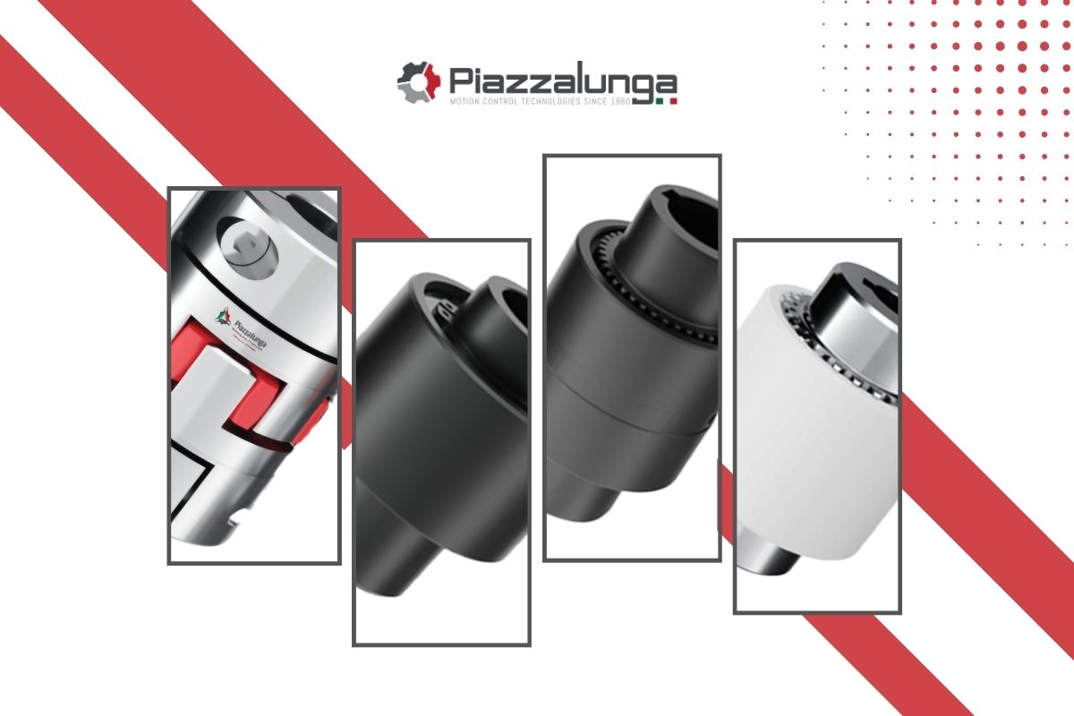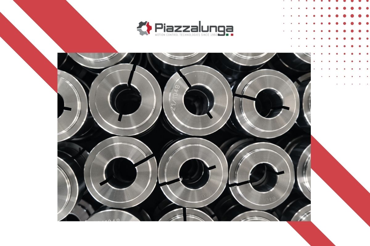
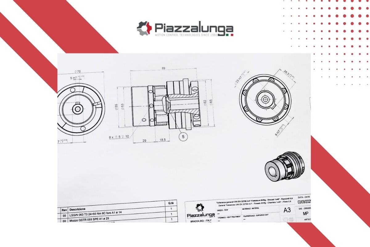
In mechanical design, one of the most common mistakes is evaluating transmission components as independent elements.
In reality, an efficient transmission system does not depend solely on the quality of each individual component, but on how the various elements interact with one another.
This is especially true for torque limiters and couplings.
When properly combined, these two components do not simply perform separate functions: they become part of an integrated system that determines the safety, precision, reliability and service life of the entire machine.
Why Torque Limiters and Couplings Should Not Be Considered Separately
The role of torque limiters is to protect the transmission from overloads by reacting quickly when torque exceeds a predefined threshold.
Couplings, on the other hand, transmit motion between two shafts and influence:
- torsional stiffness,
- misalignment compensation,
- vibration damping,
- transmission accuracy.
If torque limiters provide protection, couplings determine how the system behaves during normal operation.
Considering these two elements separately means overlooking their combined effect.
An uncoordinated selection can compromise:
- response speed,
- dynamic stability,
- component lifespan,
- overall reliability.
For this reason, the correct engineering approach is not simply selecting two components, but designing an integrated transmission solution.
When Torque Limiters and Couplings are combined
The combination of a torque limiter and a coupling is required when transmission shafts are coaxial.
In these configurations, integration allows designers to achieve:
- overload protection,
- compactness,
- controlled power transmission,
- better adaptation to the system’s dynamic requirements.
This solution is widely used in:
- automatic machinery,
- industrial production lines,
- OEM systems,
- high-precision applications.
In these contexts, coupling selection cannot be standardized: it must be defined according to the behavior required from the entire system.
Parameters that guide Coupling Selection
The choice of the coupling to be combined with a torque limiter depends on several technical factors.
Torsional Stiffness
Torsional stiffness determines how directly and accurately the system responds to motion transmission.
A stiffer coupling is ideal when the application requires:
- high precision,
- synchronization,
- immediate response.
It is often preferred in:
- servo drives,
- precision automation,
- machines requiring accurate motion control.
Vibration Damping
The use of a coupling with greater damping capability may be advantageous in case of shocks, vibrations or variable loads.
This allows designers to:
- reduce stress,
- protect mechanical components,
- increase system lifespan.
Rotational Speed
Every coupling must be compatible with the expected operating speeds.
High-speed applications require:
- proper balancing,
- dynamic stability,
- manufacturing precision.
An incorrect selection may compromise both performance and safety.
Precision and Backlash
Some applications require backlash-free transmission in order to ensure:
- accurate positioning,
- repeatability,
- process control.
In other cases, a small degree of elasticity may be beneficial to absorb stress.
The correct choice always depends on the application context.
Reliability in Real Operating Conditions
The operating environment, shaft misalignment, duty cycles and harsh working conditions directly influence component selection.
The optimal solution is not the one that looks best in theory, but the one that performs best in the real application.
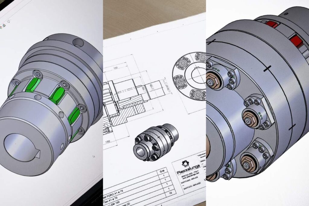
Rigid or Flexible Coupling: how system Behavior changes
The choice between a rigid coupling and a flexible coupling significantly affects transmission behavior.
Rigid Couplings
Advantages:
- high precision,
- zero backlash,
- direct dynamic response.
Ideal for:
- precision applications,
- motion control,
- servo-assisted systems.
Flexible Couplings
Advantages:
- damping capability,
- misalignment compensation,
- vibration reduction.
Ideal for:
- variable loads,
- heavy-duty applications,
- enhanced mechanical protection.
Selection must also consider the behavior of the torque limiter itself.
An unsuitable coupling can negatively affect:
- response sensitivity,
- system stability,
- service life.
The Most Common Design Mistakes in Integrated Assemblies
Many issues arise from a non-systemic selection approach.
Common mistakes include:
- selecting the torque limiter and coupling separately;
- considering only nominal torque values;
- ignoring vibrations and dynamic behavior;
- underestimating backlash;
- overlooking operating conditions.
Possible consequences:
- premature wear,
- false triggering,
- reduced precision,
- increased maintenance,
- overall inefficiency.
Designing the Transmission as a System: Concrete Advantages
When the torque limiter and coupling are designed as part of a single integrated system the benefits are significant:
- greater reliability;
- improved machine protection;
- more consistent performance;
- reduced downtime;
- longer service life;
- higher efficiency.
Moreover, this approach enables customization, an increasingly important factor in advanced industrial applications.
Conclusions: The Value of a System-Oriented Design Approach
Torque limiters and couplings should not be considered as simple components to assemble together.
The torque limiter protects the system.
The coupling defines its dynamic behavior.
Their integration determines the actual performance of the transmission.
For this reason, the most effective solution is not based on the individual product alone, but on a system-oriented design approach capable of interpreting:
- loads,
- precision requirements,
- operating environment,
- durability,
- safety.
In industrial applications, the real difference is not made by the individual component itself.
It is made by the ability to design the entire system coherently.